

How To Change Materials In Unity Animations
In Unity 2018.2 we added the "Vertex Position" input to Shader Graph, assuasive yous to adjust and animate your meshes. In this blog mail, I'll demonstrate how y'all tin create your ain vertex animation shaders, and provide some common examples such as a wind and a water shader.
If you're new to Shader Graph yous can read Tim Cooper's blog post to learn virtually the main features or watch Andy Touch'due south "Shader Graph Introduction" talk on the Unity YouTube channel.
This scene does not utilise any textures or animation avails; everything you encounter is colored and animated using Shader Graph.
Shaders are an incredibly powerful aspect of the rendering pipeline, allowing a bang-up degree of control over how our scene assets are displayed. Using a series of inputs and operations, we can create shaders that alter the various rendering backdrop of our assets, such as their surface color and texture, and even the vertex positions of the mesh. You can also combine all of these into complex, rich animations. This blog post will demonstrate how y'all can get started with vertex animations, introduce the concept of using masks and backdrop, and stop past explaining how nosotros made the shaders for the Desert Island Scene.
Download the Example Projection
Clone Repository from GitHub or Download .Zip from GitHub
Download the Desert Isle Scene sample project to start experimenting and interacting with the shaders yourself! This project contains everything yous need to go started with Shader Graph. Ensure you launch the project using Unity version 2018.2 or to a higher place.
Every shader in the Desert Island Scene was built with customization in mind, so feel gratis to start playing around with the shader values in the Inspector! Each object likewise has a preset file that will return the values to default.
This work is licensed under the Creative Commons Attribution 4.0 International License.
In order to use Shader Graph, your Project must meet the post-obit requirements:
- Running on Unity Version 2018.2 or above.
- Using either the new Lightweight or High Definition render pipelines (LWRP is suggested for experimentation due to faster compile times).
- Take the Shader Graph parcel installed in the Bundle Manager.
To install Shader Graph, either create or update a Projection to version 2018.ii or above, navigate to Window > Package Manager > All, find Shader Graph in the list and click install.
If your materials are non animative in the Scene view, make certain you lot accept Animated Materials checked:
Making something fancy with Shader Graph?
You can preview Blithe Materials by clicking the petty picture drop down at the top left of the scene view #UnityTips #Unity3D pic.twitter.com/AwxQ5jj2Sg— John O'Reilly ? (@John_O_Really) July 17, 2018
The Basics of Vertex Position
Earlier we can start using fancy maths to move things, we need to empathize what it is that we're moving.
A Mesh in the scene has four types of spaces:
- Object: Vertex position relative to the mesh pivot.
- View: Vertex position relative to the camera.
- World: Vertex position relative to the world origin.
- Tangent: Addresses some special use cases, such equally per-pixel lighting.
You can select which Space yous wish to affect in the dropdown of the Position node.
By using the Divide node we can select which axis we desire to affect.
The Split node outputs to iv channels, the first 3 represent to our Transform axis (R=X, Yard=Y, B=Z). In the example above, I've dissever out the y-centrality of the object and added 1, moving our object upwardly by ane on its own axis.
Sometimes you lot may wish to move the object in globe infinite. To practise this, select Earth from the Position node, then catechumen the output back to object infinite using the Transform node.
Now that nosotros've established how to move a Mesh, it's oft useful to know how we tin can restrict the upshot.
By using nodes such equally Lerp, we tin can alloy betwixt 2 values. The T Input is the control value for the Lerp. When our T input is 0 (visualized equally black), the A channel is used. When our input is ane (visualized equally white), the B channel is used. In the example beneath, the slider is used to blend betwixt the two inputs. Whatsoever of the post-obit examples tin can be used in identify of the slider.
With a black and white texture, we can use detailed shapes to push our Mesh. In the in a higher place example, y'all tin see how white represents the maximum height of our range, while black represents no issue on the Mesh position. This is because black has the numerical value of 0, so adding 0 to the Mesh position doesn't move it.
To use a texture with vertex position, you must use the Sample Texture 2D LOD node instead of the typical Sample Texture second node. Textures are particularly useful if yous need a mask with a unique shape or a certain caste of falloff.
While similar to a Texture mask, with a UV mask you can choose which part of the mesh y'all wish you affect based on the UV Unwrap. In the to a higher place screenshot, I'one thousand using the u-centrality of the UV to create a gradient from left to correct. To start the gradient, use an Add node; to increase the strength, utilise a Multiply node; and to increase the falloff, use a Power node.
Each vertex stores a unit of Vector3 information that we refer to as Vertex Colour. Using the Poly Brush package, we can directly paint vertex colors inside the editor. Alternatively, you tin use 3D modeling software (such as 3ds Max, Maya, Blender, 3D Coat or Modo) to assign vertex colors. It is worth noting that, past default, most 3D modeling software will consign models with the maximum value for RGB assigned to each vertex.
In the to a higher place screenshot, the Vertex Colour node is divide into the ruby (R) channel, so connected to the T aqueduct of the Lerp node, acting as a mask. The A aqueduct of the Lerp node is used when the input is 0, with the B channel being used when the input is 1. In do, the higher up set volition only add 1 to the y-centrality if the vertices accept the ruby vertex color assigned.
Past using the Normal Vector node, we tin mask an input by the orientation of the Mesh faces. Again, the Divide node allows the states to select which axis nosotros wish to affect (R=X, M=Y, B=Z). In the above screenshot, I mask using the y-axis, so that just the faces that face up are positive. It's of import to use a Clamp node to discard any values that are not betwixt 0 and 1.
This serial of nodes masks an input if the object's position is above globe position 0 on the y-axis.
When building Shaders, it can exist difficult to get the correct input values for the desired event. For this reason, and for later customization with Prefabs and presets, information technology's of import to use backdrop.
Properties permit us to modify the Shader's values after the Shader has compiled. To create a property, click the + symbol in the Blackboard (pictured on the right). At that place are six types of backdrop:
- Vectors (one to 4): A string of values, with the pick of a slider for Vector1.
- Colour: RGB values with a color picker, and an optional HDR version.
- Texture2D (and Texture2D Array): A 2D Texture sample
- Texture 3D: A 3D texture sample
- Cubemap: A generated Cubemap sample
- Boolean: An either off or on selection. Equivalent to 0 or i.
The flag Shader pans an object space sine wave beyond the flag, using a UV mask to go on the left side still.
Windy Grass and Palm Leaves
The wind Shader uses world space Gradient Noise panning along a single axis to gently push and pull the leaves and grass.
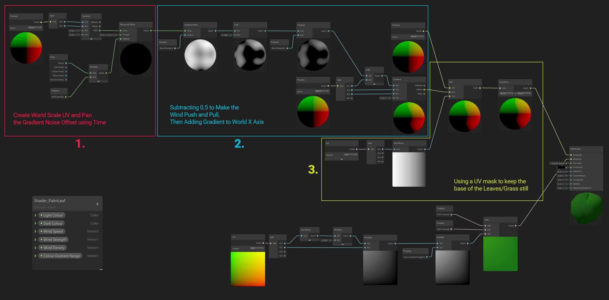
Full resolution image
- Using world position, nosotros identify a Gradient Dissonance across the y-axis and ten-axis. Using a Vector2, we tin control the speed and direction at which it is start.
- Properties are used to control the density and strength of the offset. Subtracting 0.5 from the Slope Noise ensures that the Mesh is every bit pushed and pulled.
- A UV mask is used to go on the base of the leaves and grass stationary. Finally, a Transform node is used to convert the world position to object position.
With this Shader, nosotros calculate the distance betwixt the Camera and the clam, then use this equally a mask for rotating the peak half.
In this Shader, we're using a sine wave that's generated across the object'southward centrality to make the fish wobble. We and then mask off the head of the fish, and then that the caput stays still.
Finally, we take the ocean Shader! This Shader offsets the meridian of the Mesh using three sine waves of dissimilar scales and angles. These sine waves are as well used to generate the colours for the wave troughs and tips.
Generating the Sine Waves
If you would like to know how to get started with Shader Graph, Andy Touch'southward GDC talk is a great place to start. If you're looking for other Shader Graph examples, Andy also has an Example Library available on GitHub.
For detailed documentation about Shader Graph, including descriptions of every node, become to the Shader Graph developer Wiki on GitHub. Get stuck in and join the conversation in our Graphics Experimental Previews forum! And finally, if you're making something cool with Shader Graph, I'd love to see information technology! Feel free to accomplish out to me on Twitter @John_O_Really.
Source: https://blog.unity.com/2018/10/05/art-that-moves-creating-animated-materials-with-shader-graph
Posted by: grandepoved1950.blogspot.com
0 Response to "How To Change Materials In Unity Animations"
Post a Comment